
FreeBSD
FreeBSD отличается тем, что имеет две независимые реализации механизма NAT (а значит, и технологии проброса портов). Первая носит имя natd и, как можно догадаться из названия, представляет собой демон уровня пользователя, который принимает «сырые» пакеты, выполняет необходимые преобразования адресов и отдает их обратно ядру. Вторую принято называть kernel nat, то есть механизм NAT, реализованный в ядре FreeBSD. Он позволяет выполнять преобразование адресов и проброс портов, используя правила брандмауэра ipfw.
Ясно, что вторая реализация производительнее и удобнее в использовании, и поэтому предпочтительнее. Однако kernel nat появился во FreeBSD не так давно, поэтому мы рассмотрим оба подхода на тот случай, если в твоем расп оряжении оказалась машина, использующая устаревшую версию этой операционной системы. Итак, метод номер один: natd, divert и все-все-все. Для активации NAT и проброса портов с помощью демона natd необходимо проделать следующие шаги:
1. Включить natd и ipfw в /etc/rc.conf:
2. Настроить NAT и проброс портов в /etc/natd.conf:
3. Чтобы все пакеты, проходящие через внешний интерфейс (rl1) шлюза,
перенаправлялись в natd и обрабатывались им, добавим правило divert
в /etc/ipfw.conf:
Также разрешим общение всех с внутренним сервером:
Далее можно добавить правила фильтрации. Метод номер два: ядерный NAT. Активация NAT с помощью реализации внутри ядра не требует ничего, кроме правильной настройки брандмауэра с помощью двух-трех правил. Не буду расписывать все в деталях, а просто приведу простой пример, демонстрирующий уже обсуждавшийся выше проброс 80-го порта со шлюза на внутренний сервер:
Правила ‘nat’ имеют несколько опций, большинство из которых совпадает с опциями, используемыми демоном natd. Например, опция same_ports предписывает механизму NAT сохранять оригинальные номера исходящих портов для исходящих пакетов (нужно для правильной работы некоторых RPC-протоколов). Опция rdirect_port имеет тот же синтаксис, что и в файле /etc/natd.conf.
Openwrt и DD-WRT
Конечно же, кроме оборудования именитой Cisco на рынке существуют и гораздо менее дорогостоящие решения вроде разного рода домашних роутеров и точек доступа. Большой популярностью среди них пользуются ультра-бюджетные сетевые устройства таких компаний, как D-Link, ASUS, Linksys и других. На многих из них можно установить свободные и более продвинутые прошивки вроде OpenWrt, X-Wrt и DD-wrt, которые отличаются более развитой системой настройки и хорошим комьюнити. Естественно, проброс портов легко выполнить и с их помощью. В DD-Wrt проброс портов осуществляется с помощью локализованного веб-интерфейса. Чтобы настроить проброс по описанной выше схеме, достаточно открыть веб-интерфейс роутера (192.168.1.1), перейти на вкладку «NAT/QoS», далее — вкладка «Перенаправление портов». Теперь в поле «Приложение» пишем любое удобное для нас имя, например, «www», «Порт-источник» — внешний порт роутера, «Протокол» — TCP или UDP, «IP-адрес» — адрес внутреннего сервера, «Порт-приемник» — его порт. Далее выбираем галочку «Включить», жмем кнопку «Добавить », потом — кнопку «Применить».
Это действительно простой путь, который… не сработает для большинства российских провайдеров, предоставляющих как доступ к локальной сети (прямой), так и доступ к сети интернет (через VPN/PPTP). Дело в том, что добавленное таким образом правило будет применено к внешнему физическому интерфейсу, тогда как интерфейс ppp0, используемый для выхода в интернет через VPN/PPTP, останется не при делах. Для решения проблемы можно воспользоваться прямым вмешательством в недра DD-Wrt. Открываем вкладку «Тех.обслуживание», далее — «Команды» и набираем стандартные правила iptables:
Нажимаем «Сохр. брандмауэр» и перезагружаемся. Ненамного труднее выполнить эту операцию с помощью веб-интерфейса прошивок X-Wrt, представляющих собой, по сути, более юзабельный вариант OpenWrt. Жмем на «Network», затем «Firewall», выбираем в меню «New Rule» пункт «Forward» и нажимаем «Add». Записываем в поле «Forward To» IP-адрес внутреннего сервера, в поле «Port» помещаем номер пробрасываемого порта. В выпадающем меню выбираем пункт «Protocol» и нажимаем «Add», в появившемся меню выбираем протокол: TCP или UDP. Если порт, открытый на шлюзе, должен отличаться от порта внутреннего сервера, выбираем в выпадающем меню пункт «Destination Ports», получаем одноименное поле и вводим в него номер порта. Нажимаем кнопку «Save».
Того же эффекта можно достичь, отредактировав конфигурационный файл /etc/config/firewall следующим образом:
Introduction
In order to maximize security when you implement Cisco PIX Security Appliance version 7.0, it is important to understand how packets pass between higher security interfaces and lower security interfaces when you use the nat-control, nat, global, static, access-list and access-group commands. This document explains the differences between these commands and how to configure Port Redirection(Forwarding) and the outside Network Address Translation (NAT) features in PIX software version 7.x, with the use of the command line interface or the Adaptive Security Device Manager (ASDM).
Note: Some options in ASDM 5.2 and later can appear different than the options in ASDM 5.1. Refer to the ASDM documentation for more information.
Configure Port Forwarding
To configure port forwarding, follow these steps:
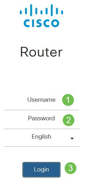
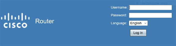
Step 1. Log in to the web configuration utility. Enter the username and password for the router and click Login. The default username and password is cisco.
In this article, we will be using the RV260 to configure port forwarding. The configuration may vary depending on the model you use.
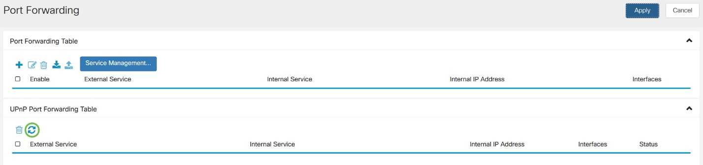
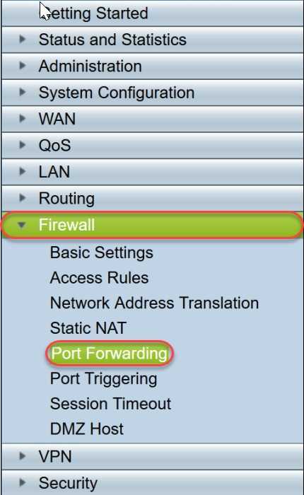
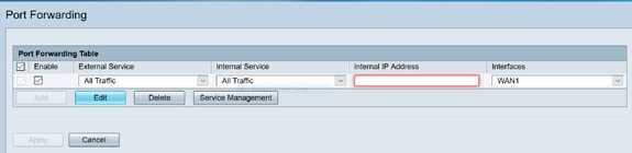
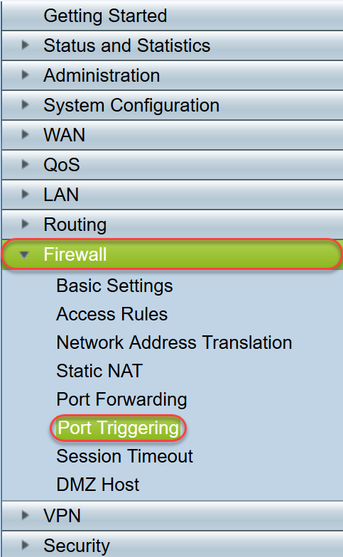
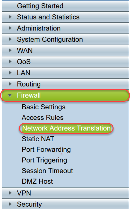
Step 2. Click Firewall > Port Forwarding.
Step 3. In the Port Forwarding Table, click add icon or select the row and click edit icon) and configure the following:
| Enable | Check Enable to enable port forwarding |
|---|---|
| External Service | Select an external service from the drop-down list. (If a service is not listed, you can add or modify the list by following the instructions in the Service Management section) |
| Internal Service | Select an internal service from the drop-down list. (If a service is not listed, you can add or modify the list by following the instructions in the Service Management section) |
| Internal IP Addresses | Enter the internal IP addresses of the server |
| Interfaces | Select the interface from the drop-down list, to apply port forwarding on |

To add or edit an entry on the Service list, follow these steps:
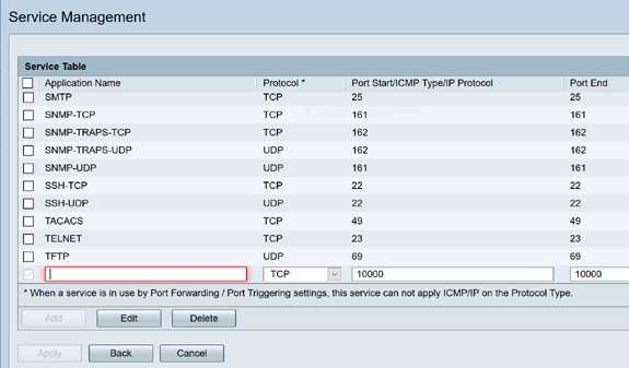
Step 4. Click Service Management.
Step 5. In the Service Management click Add icon or select a row and click Edit icon.
Configure the following:
-
Application Name — Name of the service or application.
-
Protocol — Required protocol. Refer to the documentation for the service that you are hosting.
-
Port Start/ICMP Type/IP Protocol — Range of port numbers reserved for this service.
-
Port End — Last number of the port reserved for this service.
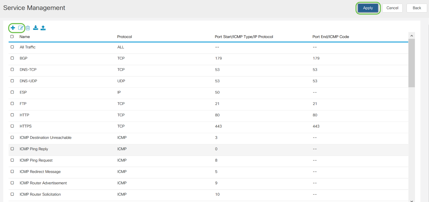
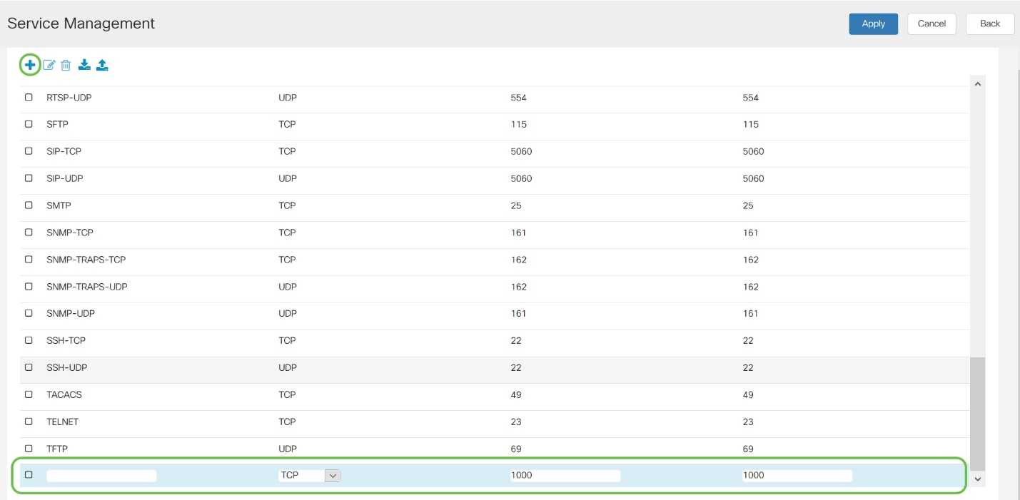
To add a service, click on the plus icon and configure Name, Protocol, Port Start/ICMP Type/IP Protocol and Port End/ICMP Code.
To edit a service, select a row and click on the edit icon to configure the fields as shown below.
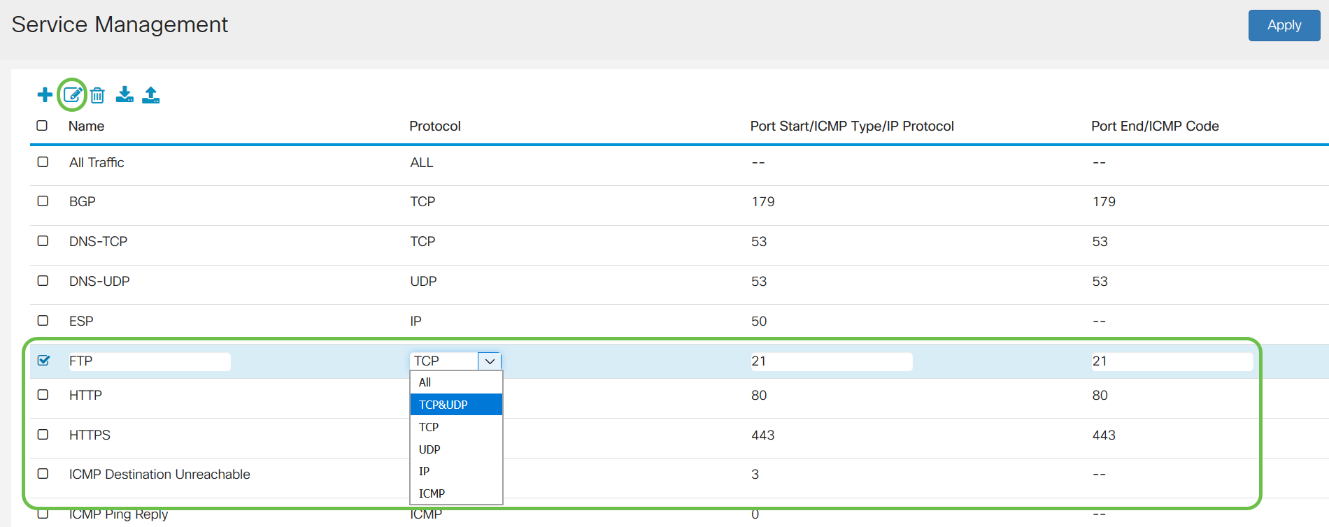
In this example, FTP service is selected.
Step 6. Click Apply.

Step 7. In the Universal Plug and Play (UPnP) Port Forwarding Table, click the refresh icon to refresh the data. The port forwarding rules for UPnP are dynamically added by the UPnP application.
Почему необходимо пробрасывать порты для доступа к внутренним ресурсам из интернета?
Такая необходимость возникает в связи с тем, что ваш роутер автоматически отфильтровывает те данные, которые вы не запрашивали. Это связано, прежде всего, с необходимостью обеспечения безопасности вашей сети. Представьте себе такую картину: у вас дома компьютер, ноутбук, хранилище файлов (файлопомойка). И ко всему этому имеет доступ любой желающий из интернета…
Чтобы не допустить всякую нечисть в домашнюю сеть, роутер пропускает только те запросы и только тому компьютеру в сети, которые он запрашивал. Для этого умные инженеры придумали NAT – Network Address Translation (преобразование сетевых адресов). Эта система позволяет скрыть от всего интернета ваш внутренний адрес. Таким образом, все устройства, подключенные к интернету в вашей домашней сети, в интернете видятся под одним единственным IP-адресом – внешним или белым. Причём, это может быть как ваш белый IP, так и просто любой провайдерский, если провайдер раздаёт внутри своей сети серые IP.
Таким образом, если вы хотите, например, подключится удалённо к вашему домашнему компьютеру через RDP – роутер просто не будет понимать, кому именно в домашней сети перенаправить запрос – вы же ему этого не объяснили… Он просто его отфильтрует. Конечно, есть ещё возможность добавить ваш домашний сервис в раздел DMZ (Demilitarized Zone) – демилитаризованную зону. Но в этом случае абсолютно все запросы извне, которые никто не запрашивал, а так же те, для которых не прописано определённое правило для портов – будут перенаправляться к вашему узлу. Таким образом вы сделаете его совершенно беззащитным, так что без острой необходимости лучше не пользоваться этим разделом в целях безопасности.
Information to Collect if You Open a Technical Support Case
| If you still need assistance and want to open a case with Cisco Technical Support, be sure to include this information for troubleshooting your PIX Security Appliance. |
|---|
Attach the collected data to your case in non-zipped, plain text format (.txt). You can attach information to your case in the TAC Service Request Tool (registered customers only) . If you cannot access the TAC Service Request Tool (registered customers only) , you can send the information in an E-mail attachment to attach@cisco.com with your case number in the subject line of your message. |
Limit TCP/UDP Session using Static
If you want to limit the TCP or UDP sessions to the internal server placed in PIX/ASA, then use the static command.
Specifies the maximum number of simultaneous TCP and UDP connections for the entire subnet. The default is 0, which means unlimited connections (Idle connections are closed after the idle timeout specified by the timeout conn command.). This option does not apply to outside NAT. The security appliance only tracks connections from a higher security interface to a lower security interface.
Limiting the number of embryonic connections protects you from a DoS attack. The security appliance uses the embryonic limit to trigger TCP Intercept, which protects inside systems from a DoS attack perpetrated by flooding an interface with TCP SYN packets. An embryonic connection is a connection request that has not finished the necessary handshake between source and destination. This option does not apply to outside NAT. The TCP intercept feature applies only to hosts or servers on a higher security level. If you set the embryonic limit for outside NAT, the embryonic limit is ignored.
For example:
%PIX-3-201002: Too many connections on {static|xlate} global_address! econns nconns
This is a connection-related message. This message is logged when the maximum number of connections to the specified static address was exceeded. The econns variable is the maximum number of embryonic connections and nconns is the maximum number of connections permitted for the static or xlate.
The recommended action is to use the show static command in order to check the limit imposed on connections to a static address. The limit is configurable.
%ASA-3-201011: Connection limit exceeded 1000/1000 for inbound packet from 10.1.26.51/2393 to 10.0.86.155/135 on interface Outside
This error message is due to Cisco bug ID CSCsg52106 (registered customers only) . Refer to this bug for more information.
Что делать, если вдруг ничего не заработало?
Есть ещё один момент, который может препятствовать доступу к сервису, который вы должны видеть из интернета. Это Firewall или Брандмауэр. А так же всякого рода антивирусы, имеющие свой Firewall и, порой параноидально, старающиеся любой ценой защитить компьютер пользователя от внешних угроз.
Попробуйте отключить ваш Firewall и проверить, будет ли доступен сервис после этого. Если всё заработает, значит нужно копать именно там.
Что именно и как копать – рассмотрим в одной из следующих статей.
Теги:
Другие статьи в разделе:
Куда девается скорость интернета?
Устанавливаем простенький FTP-сервер в среде Windows Server 2008/2012
Как настроить общий доступ к принтеру
Как организовать совместный доступ к файлам и папкам (простой способ для домашней сети)
Ограничения технологии Powerline
Как сделать интернет на даче?
Как выполнить проброс портов на маршрутизаторе
Как выбрать Powerline-адаптеры
Интернет из розетки или знакомимся с технологией Powerline
Как узнать пароль на Wi-Fi?
Как настроить роутер Apple Airport Extreme
Топологии сетей
Безопасность домашней сети
Что можно сделать с домашней сетью
Как определить IP-адрес маршрутизатора. Логины и пароли по умолчанию.
Масштабирование сетей через W-iFi
Настройка режима WDS на примере маршрутизатора ASUS WL-550gE Или как настроить повторитель
Настройка беспроводного маршрутизатора Или сеть своими руками – это просто
Сетевые технологии Или делаем сеть своими руками
My Links
- nixCraft (AWSOME Linux Tutorials)
- CCNP Guide (Awsome CCNP Notes)
- Network Geek Stuff (Awsome Network Tutorials)
- Huanetwork Blog (Nice Huawei Networking Tutorials)
- Labnario (Awsome Huawei Networking Tutorials)
- Free CCNA Workbooks (CCNAs Info + LAB)
- Online CCNA Courses
- TutorialsPoint (Multiple Programing Langues — AWSOME)
- RTL SDR Sceners (Awsome SDR Radio Tutorials)
- RTL SDR Blog (Awsome SDR Radio Blog)
- CLI Frenzy (AWSOME — Cisco Config Examples )
- Duino 4 Projects.(Tons of Arduino Projects)
- Raspberry Pi Pod (Raspberry Projects)
- Huawei From Scratch (Huawei Howtos — Very Good)
- Make Use Of (Good DIY Tutorials)
- Adafruit Learning (Arduino Lessons / Projects)
- Adafruit Learning (Raspberry Pi Lesons / Projects)
- Adafruit Learning (DYI Arduino/Raspberry Projects)
- Redes de Computadores 1 (ISEL — Muito Bom)
- Redes de Computadores 2 (ISEL — Muito Bom)
- Brezular’s Blog (Networking: Linux, Cisco & Huawei Emulators — AWSOME)
- PacketLife (Networking — Very Good)
- Visio Cafe (Networking Stencils)
- Arduino User Community (Cool Projects)
- Think Like a Computer (Articles and Howtos)
- Hak5 (Hacking Shows)
- Hacks Tips (Howtos — Very Cool)
- Web em PT (Howtos & Stuff)
- Arduino Shields (Addons)
- Arduino (Open Prototype Board)
- MigthyOHM (Cool Hw Hacks)
- ZenPacks (ZenOSS Plugins)
- ZenOSS (Network Monitoring)
- Cisco Netflow Apps
- Cisco Portugal (Blog)
- Evil Routers (Cisco IOU and More)
- Ethereal Mind (Networks Design)
- HowtoGeek (Very Good Howtos)
- Forum Routing PT
- DigitalTut (Cisco CCNP Exam Labs)
- 9Tut (Cisco CCNA Exam Labs)
- Exam Collection (IT Cert Exams)
- Career Cert (Cisco Cert Material)
- Cert Collection (IT Cert Material)
- GNS3 Vault (Cisco Labs)
- CCNA Study Online
- Cisco Router Configuration — Quick Guide
- Cisco Networking (firewall.cx)
- CBT Nuggets (Video IT Training — Microsoft, CompTIA, Cisco, Citrix)
- Viper Labs (VoiP Security Assessement Tools — Ex UCSniff)
- Ireasoning (SNMP & MIB Tools — Scan, Development, Test)
- MikroTik (Router OS and NT Apps)
- HTCPedia (Customizing HTC Phones)
- Android PT (Apps, Howtos — PT)
- Android Developers (Programing Android)
- Pen Drive Apps (Free Portables Apps)
- Pen Drive Linux (Linux on a PEN)
- Think Free, Think Open (Blog)
- PcWinTech (Apps, Howtos and more)
- Turnkey Linux (Free Virtual Appliances)
- VMWare Virtual Appliances (Free)
- SpiceWorks (Network Mngt Apps)
- SolarWinds (Networking Apps)
- Gadmintools (Guis for Linux)
- FlashBay (Custom PENs)
- Networking Tutorial
- Kit Emprego
- OpenManiak (Network an Security)
- SECTOOLS (NMAP)
- NirSoft (passwords and network tools)
- BASH Programming — Intro
- FTTx Tutorial
- ISEP Networking, Unix e +
- Linux Alternatves to Windows Software
- Pagina do Eitch (Tutorias Linux e Programação )
- My Penguin News
- My Howtos and Projects (WebPage)
- Howto Geek (very cool an funny)
Другие подходы
Для осуществления проброса порта совсем необязательно использовать брандмауэры или системные демоны, как, например, этого требуют старые версии FreeBSD. Существует несколько других способов сделать это с помощью специализированного софта или стандартных инструментов ОС (кто знает, возможно, ты используешь Minix в качестве ОС для шлюза :)). Один из таких инструментов — SSH. Далеко не каждый системный администратор в курсе, что проброс порта является стандартной функцией этой программы. Возьмем, к примеру, следующую ситуацию. В локальной сети, закрытой от внешней сети NAT’ом, есть сервер, к которому тебе необходимо иметь доступ. Ситуация усугубляется тем, что ты не имеешь привилегий для настройки файервола на машине-шлюзе. Зато у тебя есть доступ к SSH-серверу, работающему на этом шлюзе. Как это может помочь? На самом деле очень сильно. Ты просто выполняешь следующую команду на удаленной машине (serverip — адрес внутреннего сервера, gateway-ip — адрес шлюза):
И вуаля, порт 8080 локальной машины становится портом 80 внутреннего сервера локалки. Теперь достаточно набрать в веб-браузере адрес localhost:8080, и ты попадешь туда, куда надо. Твой SSH-клиент создаст туннель с SSH-сервером шлюза, все передаваемые в рамках которого данные будут направлены на порт 80 внутреннего сервера.
Более радикальный способ — установка софта, специально созданного для осуществления проброса портов. Одна из таких программ носит имя rinetd и представляет собой высокопроизводительный сервер, позволяю щий пробрасывать любое количество соединений. Он есть в пакетах для популярных Linux-дистрибутивов и портах BSD-систем.
После его установки достаточно отредактировать файл /etc/rinetd.conf (/usr/local/etc/rinetd.conf), поместив туда строки следующего вида:
И (пере)запустить сервер командой:
в Ubuntu или:
во FreeBSD. Так же во FreeBSD придется активировать запуск rinetd при
старте:
После этого весь трафик, пришедший на порт 80 машины 1.2.3.4, будет автоматически перенаправлен на тот же порт машины с IP-адресом 192.168.0.100.
Один из излюбленных способов проброса портов среди UNIX-администраторов заключается в использовании утилиты socket совместно с сетевым супер-сервером inetd. Как и все гениальное, идея в этом случае проста, а реализация очевидна. Открываем файл /etc/inetd.conf (даже если в твоей системе используется более новый xinetd, ты все равно можешь использовать этот файл) и добавляем в него строку следующего вида:
Здесь порт1 — это прослушиваемый порт на машине-шлюзе, а порт2 — порт назначения на внутренней машине 192.168.0.100. При этом оба они должны быть заданы в форме имени службы (www, ftp и т.д.), если же таковой не имеется (ты выбрал произвольный порт), то ее необходимо добавить в файл /etc/services.
Далее можно перезагрузить inetd командой «kill -HUP» и наслаждаться результатом. Если же его нет, то смотрим в файл /etc/hosts.allow. Доступ к службе должен быть открыт.
Introduction
Cisco IOS Network Address Translation (NAT) is designed for IP address simplification and conservation. It enables private IP internetworks that use nonregistered IP addresses to connect to the Internet. NAT operates on a Cisco router that connects two networks together, and translates the private (inside local) addresses in the internal network to public addresses (outside local) before packets are forwarded to another network. As a part of this functionality, you can configure NAT to advertise only one address for the entire network to the outside world. This effectively hides the internal network from the world. Therefore, it provides additional security.
Option 1: Port Forwarding Using ASDM
Note: This option uses ASDM Version 7.9(2) If yours is older ;
Connect to the ASDM, Configuration > Firewall > NAT Rules > Right Click ‘Network Object Nat Rules’ > Add ‘Network Object’ Nat Rule.
Name = “Give the internal server/host a sensible name” > Type = Host > IP Address = The internal / private IP address > Type = Static > Translated address = Outside > Advanced > Source Interface = Inside > Destination Interface = Outside > Protocol = TCP > Real port = http > Mapped Port = http > Ok > OK > Apply.
Note: This assumes your Outside interface is called outside, Inside interface is called inside and you want to port TCP port 80 (http).
Configuration > Firewall > Access Rules > Right Click ‘Outside Interface” > Add Access Rule.
Interface = Outside > Action = Permit > Source = Any > Destination {Browse} > Locate the object you created earlier > Add to Destination > OK.
Service {Browse} > Select the Port you require (i.e. http) > OK.
OK > Apply > When you have tested it works, save the changes.
Setting Up Port Forwarding and Port Triggering
Port Forwarding
To configure port forwarding, follow these steps:
Step 1. Log in to the web configuration utility. Enter the IP address for the router in the search/address bar.
The browser might issue a warning that the website is untrusted. Continue to the website. For more guidance with
this step, click here.
Enter the username and password for the router and click Log In. The default username and
password is cisco.
Step 2.From the main menu on the left side,Click Firewall > Port Forwarding
In the Port Forwarding Table, click Add or select the row and click Edit to configure the
following:
|
External Service |
Select an external service from the drop-down list. (If a service is not listed, you can add or |
|
Internal Service |
Select an internal service from the drop-down list. (If a service is not listed, you can add or |
|
Internal IP Address |
Enter the internal IP addresses of the server. |
|
Interfaces |
Select the interface from the drop-down list, to apply port forwarding on. |
|
Status |
Enable or disable the port forwarding rule. |
For example, a company hosts a web server (with an internal IP address of 192.0.2.1) on their LAN. A port
forwarding rule for HTTP traffic could be enabled. This would allow requests from the internet into that
network. The company sets the port number 80 (HTTP) to be forwarded to IP address 192.0.2.1, then all HTTP
requests from outside users will be forwarded to 192.0.2.1. It is set up for that specific device in the
network.
Step 3 .Click Service Management
In the Service Table, click Add or select a row and click Edit and configure the following:
- Application Name – Name of the service or application
- Protocol – Required protocol. Refer to the documentation for the service that you are hosting
- Port Start/ICMP Type/IP Protocol – Range of port numbers reserved for this service
- Port End – Last number of the port, reserved for this service
Step 4. Click Apply
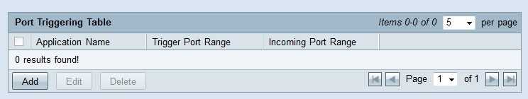
Port Triggering
To configure port triggering, follow these steps:
Step 1.Log in to the web configuration utility. From the main menu on the left side,click Firewall >
Port Triggering
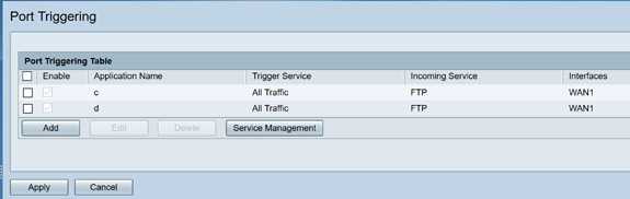
Step 2.To add or edit a service to the port triggering table, configure the following:
|
Application Name |
Enter the name of the application. |
|
Trigger Service |
Select a service from the drop-down list. (If a service is not listed, you can add or modify the |
|
Incoming Service |
Select a service from the drop-down list. (If a service is not listed, you can add or modify the |
|
Interfaces |
Select the interface from the drop-down list. |
|
Status |
Enable or disable the port triggering rule. |
Click Add (or select the row and click Edit) and enter the following information:
Step 3 . Click Service Management, to add or edit an entry on the Service list.
In the Service Table, click Add or Edit and configure the following:
- Application Name – Name of the service or application
- Protocol – Required protocol. Refer to the documentation for the service that you are hosting
- Port Start/ICMP Type/IP Protocol – Range of port numbers reserved for this service
- Port End – Last number of the port, reserved for this service
Step 4 .Click Apply
Network Address Translation
Network address translation (NAT) enables private IP networks with unregistered IP addresses to connect to the
public network. This is a commonly configured protocol in most networks. NAT translates the private IP addresses
of the internal network to public IP addresses before packets are forwarded to the public network. This allows a
large number of hosts on an internal network to access the internet through a limited number of public IP
addresses. This also helps to protect the private IP addresses from any malicious attack or discovery as the
private IP addresses are kept hidden.
To configure NAT, follow these steps
Step 1.Click Firewall> Network Address Translation
Step 2. In the NAT Table, check Enable NAT for each applicable Interface on the list to enable
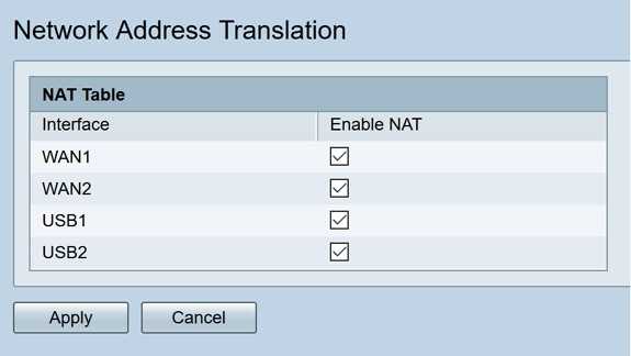
Step 3. Click Apply
You have now successfully configured Port forwarding, Port Triggering, and NAT.
Other Resources
- For configuration of Static NAT, click here
- For answers to many questions about routers, including the RV3xx series, click here
- For FAQs on RV34x series, click here
- For more information on RV345 and RV345P, click here
- For more information on configuring Service Management on the RV34x series, click here
Configure
In this section, you are presented with the information you can use to configure the features described in this document.
Note: In order to find additional information on the commands used in this document, refer to the IOS Command Lookup tool (registered customers only) .
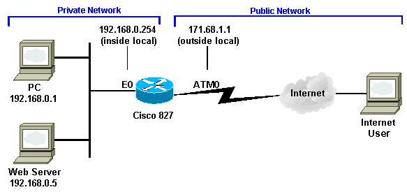
This document uses this network setup.

Configuration
| Cisco 827 |
|---|
Current Configuration: ! version 12.1 service timestamps debug uptime service timestamps log uptime ! hostname 827 ! ip subnet-zero no ip domain-lookup ! bridge irb ! interface Ethernet0 ip address 192.168.0.254 255.255.255.0 ip nat inside ! interface ATM0 no ip address no atm ilmi-keepalive pvc 0/35 encapsulation aal5snap ! bundle-enable dsl operating-mode auto bridge-group 1 ! interface BVI1 ip address 171.68.1.1 255.255.255.240 ip nat outside ! ip nat inside source list 1 interface BVI1 overload ip nat inside source static tcp 192.168.0.5 80 171.68.1.1 80 extendable ip classless ip route 0.0.0.0 0.0.0.0 171.68.1.254 ! access-list 1 permit 192.168.0.0 0.0.0.255 bridge 1 protocol ieee bridge 1 route ip ! end |
Port Forwarding and Port Triggering
Step 1. Log in to the web configuration utility and choose Setup > Forwarding. The Forwarding page opens:
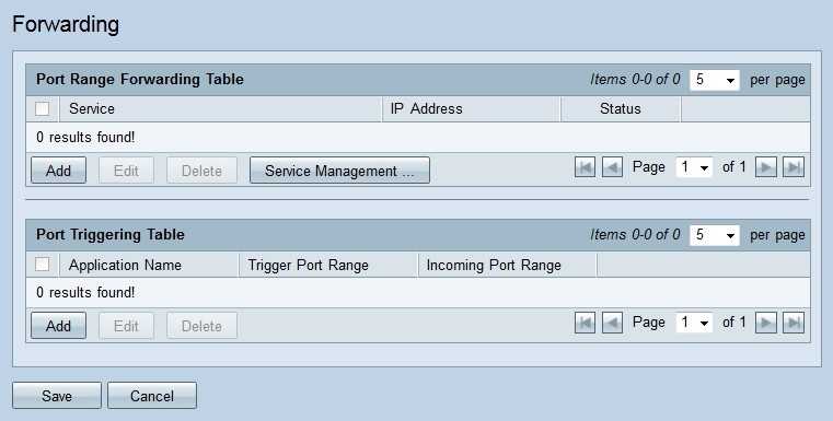
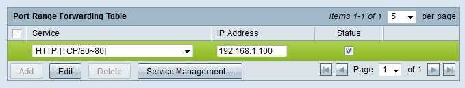
Add Port Range Forwarding
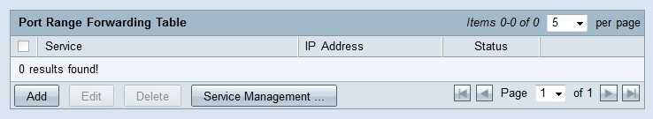
Step 1. Click Add in the Port Range Forwarding Table to add a range of ports to be opened
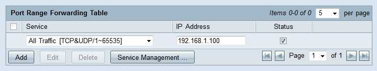
Step 2. From the Service drop-down list choose a service to open ports for.
Note: Click Service Management to add or edit a service. is discussed later in the article.
Step 3. Enter the IP address to which the traffic is to be forwarded in the IP address field.
Step 4. Check the check box in the Status field to open the configured ports.
Step 5. Click Save. The port forwarding configuration is saved.
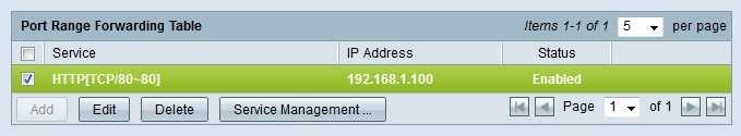
Edit Port Range Forwarding
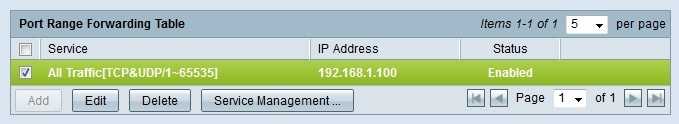
Step 1. Check the check box of the port range you want to edit.
Step 2. Click Edit in the Port Range Forwarding Table to edit the port range.
Step 3. From the Service drop-down list choose a service to open ports for.
Note: Click Service Management to add or edit a service. is discussed later in the article.
Step 4. Edit the IP address to which the traffic is to be forwarded in the IP address field.
Step 5. Check the check box in the Status field to open the configured ports.
Step 6. Click Save. The port forwarding configuration is updated.
Delete Port Range Forwarding
Step 1. Check the check box of the port range that you want to delete.
Step 2. Click Delete to delete the specific port range configuration.
Step 3. Click Save. The port range configuration is deleted.
Add Port Range Triggering
Step 1. Click Add in the Port Triggering Table to add a port trigger.
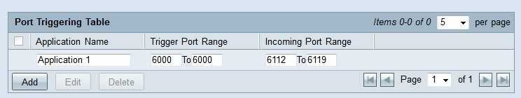
Step 2. Enter the name of the application that you want to configure ports for in the Application Name field.
Step 3. Enter the trigger port range in the Trigger Port Range field. These are the ports that you want to trigger the rule.
Step 4. Enter the forwarded port range in the Forwarding Port Range field. These are the ports that are forwarded when the rule is triggered.
Step 5. Click Save. The port triggering configuration is saved.
Edit Port Triggering

Step 1. Check the check box of the port trigger you want to edit.
Step 2. Click Edit in the Port Triggering Table to edit the port trigger.
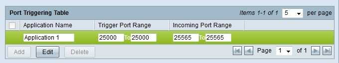
Step 3. Edit the name of the application that you want to configure ports for in the Application Name field.
Step 4. Edit the trigger port range in the Trigger Port Range field. These are the ports that you want to trigger the rule.
Step 5. Edit the forwarded port range in the Forwarding Port Range field. These are the ports that are forwarded when the rule is triggered.
Step 6. Click Save. The port triggering configuration is updated.
Delete Port Triggering
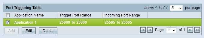
Step 1. Check the check box of the port trigger that you want to delete.
Step 2. Click Delete to delete the specific port trigger configuration.
Step 3. Click Save. The port trigger configuration is deleted.
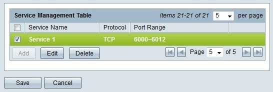
Add Service Name
Step 1. Click Service Management. The Service Management window appears.
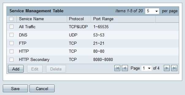
Step 2. Click Add to add a new service.
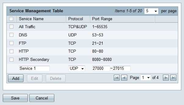
Step 3. Enter a name for the service in the Service Name field.
Step 4. From the protocol drop-down list choose the protocol that the service uses.
- TCP — The service forwards Transmission Control Protocol (TCP) packets.
- UDP — The service forwards User Datagram Protocol (UDP) packets.
- IPv6 — The service forwards all IPv6 traffic.
Step 5. If the protocol is either TCP or UDP, enter the range of ports that is reserved for the service in the Port Range field.
Step 6. Click Save. The service is saved to the Service Management Table.
Edit Service Name
Step 1. Click Service Management. The Service Management window appears.
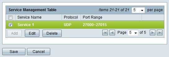
Step 2. Check the check box of the service you want to edit.
Step 3. Click Edit to edit the service.
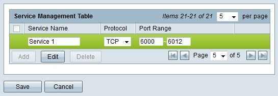
Step 4. Edit the name for the service in the Service Name field.
Step 5. From the protocol drop-down list choose the protocol that the service uses.
- TCP — The service forwards Transmission Control Protocol (TCP) packets.
- UDP — The service forwards User Datagram Protocol (UDP) packets.
- IPv6 — The service forwards all IPv6 traffic.
Step 6. If the protocol is either TCP or UDP, enter the range of ports that is reserved for the service in the Port Range field.
Step 7. Click Save. A warning window appears. Any configuration that is associated with the edited service is automatically updated.

Step 8. Click Yes. The service configuration is updated.
Delete Service Name
Step 1. Click Service Management. The Service Management window appears.
Step 2. Check the check box of the service you want to delete.
Step 3. Click Delete to delete the service.
Step 4. Click Save. A warning window appears. Any configuration that is associated with the deleted service is automatically deleted.
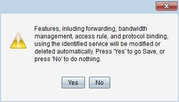
Step 5. Click Yes. The service is deleted.
You have now learned the steps to configure port forwarding and port triggering on the RV32x VPN Router Series.
Verify
From the show ip nat translation command output, the Inside local is the configured IP address assigned to the Web server on the inside network. Notice that 192.168.0.5 is an address in the private address space that cannot be routed to the Internet. The Inside global is the IP address of the inside host, which is the Web server, as it appears to the outside network. This address is the one known to people who try to access the Web server from the Internet.
The Outside local is the IP address of the outside host as it appears to the inside network. It is not necessarily a legitimate address. But, it is allocated from an address space that can be routed on the inside.
The Outside global address is the IP address assigned to a host on the outside network by the owner of the host. The address is allocated from an address or network space that can be globally routed.
Notice that the address 171.68.1.1 with port number 80 (HTTP) translates to 192.168.0.5 port 80, and vice versa. Therefore, Internet users can browse the Web server even though the Web server is on a private network with a private IP address.
In order to get more information about how to troubleshoot NAT, refer to the Verifying NAT Operation and Basic NAT Troubleshooting.