
Implementation Restrictions
EtherChannel has certain implementation restrictions, including the following:-
- In Port channel there are some restrictions which must be followed. Let’s take an example, Fast Ethernet and Gigabit Ethernet can not be mixed with a single port channel. All ports must be the same either all should be Fast Ethernet ports, or all ports should be Gigabit Ethernet ports.
- Each EtherChannel can consist of up to eight compatible configured ports. They can have 8 Gbps full duplex bandwidth between one switch to another switch.
- The Cisco Catalyst 2960 Layer 2 switch currently supports up to six EtherChannel’s.
- The individual EtherChannel group member port configuration must be consistent on both devices. If the physical ports of one side are configured as trunks, the physical ports of the other side must also be configured as trunks within the same native VLAN. Additionally, all ports in each EtherChannel link must be configured as Layer 2 Ports.
- Each EtherChannel has a logical port channel interface. A configuration applied to the port channel interface affects all physical interfaces that are assigned to that interface.
EtherChannel’s or Port Channel can be formed through negotiation using one of two protocols:-
- Port Aggregation Protocol (PAgP)
- Link Aggregation Control Protocol (LACP)
These protocols do allow ports with having same characteristics while making port channel through dynamic negotiation.
Introducing PortChannels
What is a PortChannel?
A PortChannel is a logical association of physical links, that make them look like a single one. You can configure that logical interface like any other: set an IP address, configure it as a trunk, enable PortFast, and so on. All the configurations will be automatically replicated to the children physical interfaces.
You can bundle into a PortChannel interface on the same type only. For example, you can’t put a FastEthernet interface in the same PortChannel where you put a GigabitEthernet. Furthermore, each switch has a limitation on how many interfaces can join the same PortChannel. Most of the time, it is 8: you can have a PortChannel relying on up to 8 physical links.
For a PortChannel to work, both devices at its ends must agree on it. They must know that they are talking over a PortChannel, and to treat it like a single link. If a device treats some physical links as part of a PortChannel, but the other device doesn’t, these links will be down. As we will see in the next section, we have different options to create a port channels.
PortChannel modes and Protocols
Not all PortChannels are made equal. You can have some static, and some dynamic, but there’s more. Dynamic port channels can have a master on one side.
With a static PortChannel, you need to hardcode on both devices the existence of the PortChannel. Then, they will start to treat the links as a bundle, as simple as that. However, if one of the two devices is misconfigured, the other will notify out-of-order packets and will shut down the link. This is probably the easiest way and the preferred one when a device doesn’t support a negotiation protocol.
To have a more scalable approach, you can use a dynamic protocol to negotiate the existence of the PortChannel. You have two choices, Link Aggregation Control Protocol (LACP) and Port Aggregation Protocol (PAgP). These are not interoperable, so both devices need to talk the same protocol.
LACP is the standard version (IEEE 802.3ad), and it is widely accepted. You are going to find LACP on Switches from different vendors, and on servers. If you configure a port to work in LACP, it will start to work as a standalone, like any other physical port. However, it will start to send (and listen for) LACP messages. In case it finds an LACP peer on the other side, the port will be automatically added to the bundle. This protocol has two modes, active and passive. As you can tell, an active port will actively try to make the bundle, while a passive one will wait for the device on the other side to initiate.
As a last option, with have PAgP, the Cisco proprietary aggregation protocol. It works exactly like LACP, but only Cisco supports it. So, what’s the point in using it? Nowadays, there’s no point: use LACP whenever you can.
Inside a PortChannel
No matter if you hardcode ports statically or if a dynamic protocol negotiated them: once they are in the bundle, they are in the bundle. Now that the bundle contains multiple ports, how will the switch select which packet send through which physical ports? This is where hashing comes in.
Each physical port is associated with a specific identifier, the hash. Once a packet arrives on the switch, and the switch understands that it should go on a PortChannel, it runs a hash function on the headers. All in all, it takes the source and destination addresses (IP, MAC, Layer 4 ports) and with some mathematical calculations obtain a hash from it. Then, the packet is sent to the port with that hash.
Since the hash works well only with the power of two, your PortChannel should always have a number of links which is the power of 2 (2, 4, 8). Don’t use any other such as 3 or 6, because traffic won’t be optimized. In fact, in case you have such a number, a link might run 2 hashes, having twice the traffic of the others. For example, if you have three links, the hash function will divide traffic for four hashes, but one link will have hash 3 and hash 4.
Do PortChannels increase bandwidth? Yes, however, not on a single flow. The same flow will be hashed always on the same link, so it will get the bandwidth of that link as ceiling. Instead, we can see that the bandwidth of a PortChannel is the bandwidth of all its physical ports if many flows run on it.
Tip: to optimize the distribution of traffic, you can select what to use in the hash function (e.g. source MAC). Change it according to your needs.
Link Aggregation Control Protocol (LACP)
LACP provides the same negotiation benefits as PAgP. LACP helps create the EtherChannel link by detecting the configuration of each side and making sure that they are compatible so that the EtherChannel link can be enabled when needed. The modes for LACP are as follows:-
- On : This mode forces the interface to channel without LACP. Interfaces configured in the on mode do not exchange LACP packets.
- LACP active : This LACP mode places a port in an active negotiating state. In this state, the port initiates negotiations with other ports by sending LACP packets.
- LACP passive : This LACP mode places a port in a passive negotiating state. In this state, the port responds to the LACP packets that it receives but does not initiate LACP packet negotiation.
Verify or Troubleshooting the Port Channel / EtherChannel
The steps which we have discussed are very simple and easy to configure the port channel. When you configure the device in your network, one should always check and verify the configurations. If there are some problems or errors, you need to understand and should be able to handle the problems or fix it. There are several commands to verify an EtherChannel configuration.
- The show interfaces port-channel command displays the general status of the port channel interface.
- The show interfaces EtherChannel command can provide information about the role of a physical member interface of the EtherChannel.
- The show EtherChannel summary command displays one line of information per port channel.
- The show EtherChannel port-channel command displays detailed information about a specific port channel interface.
All interfaces within an EtherChannel must have the same configuration of speed and duplex mode, native and allowed VLANs on trunks, and access VLAN on access ports. Ensuring these configurations will significantly reduce network problems related to EtherChannel. Common EtherChannel issues include the following:-
- Assigned ports in the EtherChannel are not part of the same VLAN, or not configured as trunks. Ports with different native VLANs cannot form an EtherChannel.
- Trunking was configured on some of the ports that make up the EtherChannel, but not all of them. It is not recommended that you configure trunking mode on individual ports that make up the EtherChannel. When configuring a trunk on an EtherChannel, verify the trunking mode on the EtherChannel.
- If the allowed range of VLANs is not the same, the ports do not form an EtherChannel even when PAgP is set to the auto or desirable mode.
- The dynamic negotiation options for PAgP and LACP are not compatibly configured on both ends of the EtherChannel.
Configuration Guidelines
There are some important guidelines and restrictions for configuring the port channel:-
- EtherChannel support : All the ethernet interfaces must support port channel as there should not be any problem in the physical layer of the interface.
- Speed and duplex : Configure all interfaces in an EtherChannel to operate at the same speed and in the same duplex mode.
- VLAN match : All interfaces in the EtherChannel must be in the same VLAN or should be act as trunking.
- Range of VLANs : An EtherChannel supports the same allowed range of VLANs on all the interfaces in a trunking EtherChannel. If the allowed range of VLANs is not the same, the interfaces do not form an EtherChannel, even when they are set to auto or desirable mode.
Advantages of EtherChannel
EtherChannel technology has many advantages, including the following:-
- The configuration on Port channel is comparatively easy instead of on each individual port, ensuring configuration consistency throughout the links.
- EtherChannel relies on existing switch ports. There is no need to upgrade the link to a faster and more expensive connection to have more bandwidth.
- Load balancing takes place between links that are part of the same EtherChannel.
- Ether Channel do provide redundancy because the overall link is considered as one logical channel. It does not create loop or change in the topology. This technique is very useful in the switching and makes the life of a network administrator easy.
Real World Application & Core Knowledge
If you completely the previous three labs then you should be quite familiar with EtherChannel technology by now. As stated in the previous labs that when you bundle multiple links into an etherchannel they are represented by a single logical link, or you can say a single logical interface which is known as a port-channel interface.
Port-Channel interfaces are classified as “virtual links” which will represent the path that traffic traverses when going through an etherchannel bundle towards a specific destination.
Any commands issued in Port-Channel configuration mode apply to all links in the channel-group.
In this lab you will familiarize yourself with the following commands;
| Command | Description |
|---|---|
| interface port-channel # | When executing this command in global configuration mode you will be placed in Port-Channel interface configuration mode which configures all bundled links in the specific Ether-Chanel group number simultaneously. |
Port Aggregation Protocol (PAgP)
Let’s have some explanation of the Port aggregation protocol. PAgP is a Cisco-proprietary protocol that aids in the automatic creation of EtherChannel links. When an EtherChannel link is configured using PAgP, PAgP packets are sent between EtherChannel-capable ports to negotiate the forming of a channel. When PAgP identifies matched Ethernet links, it groups the links into an EtherChannel. The EtherChannel is then added to the spanning tree as a single port.
When it is enabled, PAgP also manages the Ether Channel. This sent packets every 30 seconds. It also checks the configuration and manages the links additions and failures between the two switches. It also makes sure to have Port channel created and all ports are having the same type of configuration.
LACP is part of an IEEE specification (802.3ad) that allows several physical ports to be bundled to form a single logical channel. LACP allows a switch to negotiate an automatic bundle by sending LACP packets to the other switch. It performs a function similar to PAgP with Cisco EtherChannel. Because LACP is an IEEE standard, it can be used to facilitate EtherChannels in multivendor environments. On Cisco devices, both protocols are supported.
Lab Instruction
Step 1. – Configure interface Port-Channel1 on both SW1 and SW1 to trunk then verify that the changes you’ve made on the Port-Channel interface have propagated to the bundled links; Fa0/10, Fa0/11 and Fa0/12.
Navigate to the Port-Channel1 interface and configure the interface to trunk; afterward verify that the configuration has propagated to the bundled interfaces as shown below;
SW1 con0 is now available


Press RETURN to get started.


SW1>enable
SW1#configure terminal
Enter configuration commands, one per line.  End with CNTL/Z.
SW1(config)#interface port-channel 1
SW1(config-if)#switchport mode trunk
%EC-5-UNBUNDLE: Interface Fa0/10 left the port-channel Po1
%EC-5-UNBUNDLE: Interface Fa0/11 left the port-channel Po1
%EC-5-UNBUNDLE: Interface Fa0/12 left the port-channel Po1
%EC-5-BUNDLE: Interface Fa0/12 joined port-channel Po1
%EC-5-BUNDLE: Interface Fa0/11 joined port-channel Po1
%EC-5-BUNDLE: Interface Fa0/10 joined port-channel Po1
%DTP-5-TRUNKPORTON: Port Fa0/10-12 has become dot1q trunk
%LINK-3-UPDOWN: Interface Port-channel1, changed state to up
SW1(config-if)#end
SW1#show run
!
interface FastEthernet0/10
 switchport mode trunk
 channel-group 1 mode on
!
interface FastEthernet0/11
 switchport mode trunk
 channel-group 1 mode on
!
interface FastEthernet0/12
 switchport mode trunk
 channel-group 1 mode on
!
SW1#
As shown above when the trunk was configured on the Port-Channel 1 interface, all interface members of the channel-group were removed from the group, configuration applied then re-added to the channel-group.
Step 2. – Shutdown interface Port-Channel1 and verify that the command issued in Port-Channel1 interface configuration mode is executed on the channel-group bundled links as shown below;
SW1#configure terminal
Enter configuration commands, one per line.  End with CNTL/Z.
SW1(config)#interface port-channel 1
SW1(config-if)#shutdown
%EC-5-UNBUNDLE: Interface Fa0/10 left the port-channel Po1
%EC-5-UNBUNDLE: Interface Fa0/11 left the port-channel Po1
%EC-5-UNBUNDLE: Interface Fa0/12 left the port-channel Po1
%DTP-5-NONTRUNKPORTON: Port Fa0/10-12 has become non-trunk
SW1(config-if)#
%LINEPROTO-5-UPDOWN: Line protocol on Interface Port-channel1, changed state to down
%LINK-5-CHANGED: Interface FastEthernet0/10, changed state to administratively down
%LINK-5-CHANGED: Interface FastEthernet0/11, changed state to administratively down
%LINK-5-CHANGED: Interface FastEthernet0/12, changed state to administratively down
SW1(config-if)#
%LINK-5-CHANGED: Interface Port-channel1, changed state to administratively down
SW1(config-if)#do show run
!
interface FastEthernet0/10
 switchport mode trunk
 shutdown
 channel-group 1 mode on
!
interface FastEthernet0/11
 switchport mode trunk
 shutdown
 channel-group 1 mode on
!
interface FastEthernet0/12
 switchport mode trunk
 shutdown
 channel-group 1 mode on
!
SW1#
Troubleshooting PortChannels
Sometimes, PortChannels are just broken. This often happens when someone moves cables around in the switch closed, breaking a PortChannel. As a network engineer, you need to assess if all the ports are part of the group or if something isn’t working. We have plenty of commands to do that, but we are going to need only one.
Interestingly, Cisco names Link Aggregation PortChannels when naming the interface and channel groups when working on the physical port. Well, for the “show” commands, we have even another name: EtherChannels. Don’t worry, they are all the same thing.
A summary of PortChannels
To have an overview of the link aggregations on your switch, you can simply use . This commands will tell everything you need and has basically the same information of . Only, this command has a more compact output.
 An overview of the configured PortChannels.
This output is extremely easy to read, thanks to the Flags explanation part. For each LAG, it tells you the ID (in the field “group”) and the interface name. Next to it, it tells you the overall status of the PortChannel using flags. In there, we always want to see at least a “U”, meaning “in use”.
After that, we see the Protocol of this channel, and then the list of physical ports in it. For each of them, we have a flag indicating the status. If you don’t see a P in here, then something is wrong. 99% of the time, it is in the configuration, so double-check it.
Port Channel Implementation and Troubleshooting on Cisco Switches
Also Read: How to configure UDLD Protocol in Cisco Switches
EtherChannel is a link aggregation whose primarily function is to make on logical link of various groups of physical ethernet links. It is used to provide fault-tolerance, load sharing, increased bandwidth, and redundancy between switches, routers, and servers. EtherChannel technology makes it possible to combine the number of physical links between the switches to increase the overall speed of switch-to-switch communication.
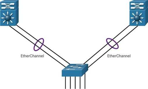
EtherChannel or port channel, the concept was developed by Cisco as a LAN switch to switch technique which was grouping of several fast ethernet or Gigabit Ethernet ports into one logical channel. When an EtherChannel is configured, the resulting virtual interface is called a port channel. The physical interfaces are bundled together into a port channel interface, as shown in the figure.
PortChannels Lab Intro
The Topology
We can use PortChannels literally everywhere. Switches, routers, and even servers supports them. Nonetheless, for this lab we are going to use simple switches, to verify the STP benefit. We have three different options to create a PortChannel, so we needed four switches in a chain to create three pairs of links in total. Here’s what the topology looks like.
 The topology for this lab.
We decided to push things a little bit further, using the same interfaces on all switches. Specifically, and use and between each other, while and uses and . Instead, and use both and between each other. This will help you a lot in the configuration.
The Requirements
Three links mean three requirements, pretty straightforward huh? Here’s what we need to do:
- Create a static PortChannel between SW1 and SW2
- Create a dynamic PortChannel with a standard protocol between SW2 and SW3, with SW2 being the master
- Use a Cisco proprietary protocol to create a PortChannel between SW3 and SW4, where both are masters
On top of that, we need to set all the PortChannels we created to be trunks.
Configuring PortChannels
A Static Port Channel
By requirement, our connection between Switch #1 and Switch #2 should be a static PortChannel. So, we need to bundle together and on SW1. A switch can have multiple PortChannels, so we need to specify to which one we are associating the interface. In doing so, we also tell which mode to use (static, LACP, PAgP).
To do that, we enter the configuration prompt for the physical interface. Then, we use the command, where the ID identifies the PortChannel and the mode identifies the protocol. To set a PortChannel as static, the mode to use is “on”. We can conveniently apply this command to both interfaces as below.
interface range FastEthernet 0/1 - 2
 channel-group 1 mode on
The PortChannel ID is local to the switch, it doesn’t have to match on the other side. However, we still need to apply these commands on the other side. For scoring purposes, use ID 1 on SW2 too, but be aware that this is not necessary. As long as the ports are on both sides, they will form the aggregation. You can also see that every time you change the mode of a port, it will go down. If then the negotiation succeeds, it will go back up.
When you add physical interfaces to a PortChannel, the switch creates the logical interface. In this case, it is PortChannel1 (the ID), and you can configure it like any other interface. We put this interface in a trunk, on both SW1 and SW2, and we are done for this link.
interface PortChannel 1
 switchport mode trunk
A LACP PortChannel
The configuration of a PortChannel which uses LACP is similar to a static one. We still use the command, but we need to change the mode. Here, we have two options.
- will actively try to negotiate with the other device, if the negotiation succeeds the port will join the bundle
- will wait for the other side to initiate the negotiation. Of course if then the negotiation succeeds it will join the bundle
Since we want the master on SW2, we are going to configure it to be active. Also, since we already used the PortChannel 1 to talk with SW1, we are going to use 2 here.
interface range FastEthernet 0/10 - 11
 channel-group 2 mode active
Instead, on the other side (SW3), we will configure passive mode. However, on that switch we don’t have any PortChannel, so we can use the first ID, as below.
interface range FastEthernet 0/10 - 11
 channel-group 1 mode passive
Don’t forget to specify that the PortChannels we just created are trunks, as we already indicated in the previous section.
A PAgP PortChannel
For our last link, we are going to use PAgP. Like LACP, it still uses the channel-group command. However, since “active” and “passive” keywords were already taken, Cisco used two new keywords.
- indicates that the device will try to negotiate, using PAgP
- indicates that the device will wait for the other to negotiate in PAgP
Since we don’t care about who is the master, we are going to put both SW3 and SW4 into the desirable mode, using the following commands on SW3.
interface range FastEthernet 0/20 - 21
   channel-group 2 mode desirable
And these commands on SW4.
interface range FastEthernet 0/20 - 21
   channel-group 1 mode desirable
Now, set the PortChannels on both sides to be trunks, and you are done! Your score should reach 100%, but there’s more. Remember the ugly amber dots? When you started the lab, all the links on the bottom were blocked by STP. Now that they are bundled, they are not anymore. Since each switch is connected to the other with a single logical link (the PortChannel), there’s no loop anymore.
Configuring EtherChannel with LACP
Step 1: Specify the interfaces that compose the EtherChannel group using the interface range <interface_name> command in global configuration mode. The range keyword allows you to select several interfaces and configure them all together.
Step 2: Create the port channel interface with the channel-group <identifier> mode active command in interface range configuration mode. The identifier specifies a channel group number. The mode active keywords identify this as an LACP EtherChannel configuration.
Step 3: To change Layer 2 settings on the port channel interface, enter port channel interface configuration mode using the interface port-channel command, followed by the interface identifier. In the example, S1 is configured with an LACP EtherChannel. The port channel is configured as a trunk interface with the allowed VLANs specified.

Conclusion
In this article, we learned how to configure and troubleshoot PortChannels. With them, you are now able to overcome a limit of STP, having resiliency on inter-switch links. Not only this increase the performance, but it also eases the maintenance of the network and reduces the need for STP re-convergence. Here’s what you need to take with you:
- You can configure a PortChannel either static or dynamic (LACP, PAgP), but both sides must agree
- Always use a number of physical ports which is the power of 2 when creating the bundle (e.g. bundle 2 or 4 together, not 3 or 5)
- Use the command in the physical interface configuration to associate it to a PortChannel
- Use to configure the PortChannel, and reflect the configuration to the physical ports
- Troubleshoot with